

Raspberry Pi science experiments connect physical sensors to Python code and produce measurable data from the real world. This guide covers six projects that work on current Pi hardware running Bookworm: temperature and pressure logging, time-lapse photography, motion detection, automated plant monitoring, basic robotics, and data visualisation. Each project uses gpiozero or standard Python libraries, requires no deprecated tools, and produces a result you can actually use or extend.
Last tested: Raspberry Pi OS Bookworm 64-bit | May 3, 2026 | Raspberry Pi 4 Model B (4GB) | Python 3.11.2 | gpiozero 2.0
Key Takeaways
- Use
gpiozero, notRPi.GPIO, for all GPIO work on Bookworm. RPi.GPIO still installs but gpiozero is the current Raspberry Pi Foundation library with a cleaner API and active maintenance. Most Pi science tutorials still show RPi.GPIO because they were written before 2022. - Always use a virtual environment for science project Python code. Bookworm enforces PEP 668. Running
pip installwithout a venv fails with “externally-managed-environment.” Creating a venv per project also isolates sensor library versions so projects don’t interfere with each other. - The Sense HAT covers temperature, humidity, pressure, accelerometer, gyroscope, magnetometer, and an 8×8 LED display in a single board. For a science project that needs multiple sensor types, it is faster and cheaper than wiring individual sensors. The trade-off is that the onboard temperature sensor reads high due to heat from the Pi processor. Mount a separate DS18B20 or BME280 for accurate ambient temperature.
Raspberry Pi Science Experiments: Setting Up the Environment
All six projects in this guide use the same virtual environment and base packages. Set this up once and activate it for each project.
sudo apt update && sudo apt full-upgrade -y
sudo apt install python3-venv python3-pip i2c-tools -y

mkdir -p ~/science && cd ~/science
python3 -m venv venv
source venv/bin/activate

pip install gpiozero lgpio adafruit-circuitpython-bme280
  adafruit-circuitpython-dht picamera2 matplotlib pandas
Enable I2C and the camera in raspi-config:
sudo raspi-config
# Interface Options > I2C > Enable
# Interface Options > Camera > Enable
sudo reboot
Expected result: After reboot, sudo i2cdetect -y 1 shows the I2C bus without errors. If you have a BME280 connected it appears at address 0x76 or 0x77.

Project 1: Temperature and Pressure Data Logger
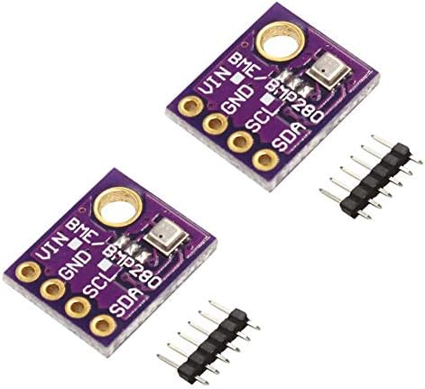
A BME280 sensor measures temperature, humidity, and barometric pressure over I2C. This project logs readings every 60 seconds to a CSV file and is the foundation for weather station, greenhouse monitoring, and HVAC experiment builds.
Hardware needed: BME280 breakout board, four female-to-female jumper wires. Wire SDA to GPIO2 (pin 3), SCL to GPIO3 (pin 5), VCC to 3.3V (pin 1), GND to GND (pin 6).
import board
import adafruit_bme280.basic as adafruit_bme280
import csv, time
from datetime import datetime

i2c = board.I2C()
bme280 = adafruit_bme280.Adafruit_BME280_I2C(i2c)
bme280.sea_level_pressure = 1013.25  # adjust for your local altitude

with open('weather_log.csv', 'a', newline='') as f:
    writer = csv.writer(f)
    writer.writerow(['timestamp', 'temp_c', 'humidity_pct', 'pressure_hpa'])

    print('Logging. Press Ctrl+C to stop.')
    while True:
        row = [
            datetime.now().isoformat(),
            round(bme280.temperature, 2),
            round(bme280.humidity, 2),
            round(bme280.pressure, 2)
        ]
        writer.writerow(row)
        f.flush()
        print(row)
        time.sleep(60)
Expected result: A new row appears in weather_log.csv every 60 seconds. Temperature accuracy is within 1 degree C of a calibrated reference at normal indoor temperatures. Humidity accuracy is within 3%RH. Run the logger for 24 hours to capture a full diurnal cycle.
To run the logger as a background service that starts at boot, see Python Raspberry Pi for the systemd service setup.
- This Kit contains with 3pcs of digital sensor module, which can be independently enabled / disabled, which can measure n…
- The BME280 sensor is great for all sorts of weather sensing and can even be used in both I2C and SPI! For simple easy wi…
- Our BME280 Sensor is the best low-cost, precision sensing solution for measuring barometric pressure with ±1 hPa absolut…
Project 2: Time-Lapse Photography
Time-lapse photography with the Pi Camera Module 3 documents slow processes: plant growth, weather patterns, construction, chemical reactions. The picamera2 library is the correct library for Bookworm. The older picamera library does not work on the current kernel and camera stack.
Hardware needed: Camera Module 3 (standard or wide). Connect via the CSI ribbon cable to the Pi camera port with the contacts facing the Pi board.
from picamera2 import Picamera2
import time, os
from datetime import datetime

output_dir = os.path.expanduser('~/timelapse')
os.makedirs(output_dir, exist_ok=True)

cam = Picamera2()
config = cam.create_still_configuration(main={"size": (2304, 1296)})
cam.configure(config)
cam.start()
time.sleep(2)  # allow auto-exposure to settle

interval_seconds = 30   # capture every 30 seconds
total_frames = 480      # 4 hours at 30s = 480 frames

print(f'Capturing {total_frames} frames every {interval_seconds}s')
for i in range(total_frames):
    filename = os.path.join(output_dir, f'frame_{i:05d}.jpg')
    cam.capture_file(filename)
    print(f'Frame {i+1}/{total_frames}: {filename}')
    time.sleep(interval_seconds)

cam.stop()
print('Capture complete. Assemble with ffmpeg:')
Assemble the frames into a video with ffmpeg:
sudo apt install ffmpeg -y
ffmpeg -framerate 24 -i ~/timelapse/frame_%05d.jpg
  -c:v libx264 -pix_fmt yuv420p timelapse.mp4
Expected result: A timelapse.mp4 file in the current directory. At 24fps and 480 frames, the 4-hour capture plays back in 20 seconds. Adjust interval_seconds and total_frames to match your experiment duration.
See Raspberry Pi HQ Camera for using the HQ Camera with interchangeable lenses for macro or telephoto time-lapse builds.
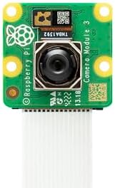
- Back-illuminated, stacked CMOS 12-megapixel Sony IMX708 image sensor
- Phase Detection Autofocus (PDAF) for rapid autofocus
- HDR mode (up to 3 megapixel output)
Project 3: Motion Detection with PIR Sensor
A PIR sensor detects changes in infrared radiation caused by warm moving objects. It is the correct sensor for presence detection, wildlife monitoring, and security trigger experiments. The gpiozero MotionSensor class wraps the GPIO read into a clean event-driven interface.
Hardware needed: HC-SR501 PIR sensor. Wire VCC to 5V (pin 2), GND to GND (pin 6), OUT to GPIO17 (pin 11). The HC-SR501 has two adjustment potentiometers: one for sensitivity (detection range, 3 to 7 metres), one for hold time (how long the output stays high after detection, 3 seconds to 5 minutes).
from gpiozero import MotionSensor
from datetime import datetime
import csv, signal, sys

pir = MotionSensor(17)
log_file = 'motion_log.csv'

with open(log_file, 'a', newline='') as f:
    writer = csv.writer(f)
    writer.writerow(['timestamp', 'event'])

def log_motion():
    ts = datetime.now().isoformat()
    print(f'Motion detected: {ts}')
    with open(log_file, 'a', newline='') as f:
        csv.writer(f).writerow([ts, 'detected'])

def log_clear():
    ts = datetime.now().isoformat()
    print(f'Motion cleared: {ts}')
    with open(log_file, 'a', newline='') as f:
        csv.writer(f).writerow([ts, 'cleared'])

pir.when_motion = log_motion
pir.when_no_motion = log_clear

print('PIR monitoring active. Press Ctrl+C to stop.')
signal.pause()
Expected result: Each motion event and clear event is timestamped and written to motion_log.csv. For wildlife monitoring, run this overnight and analyse the log to determine activity patterns. The HC-SR501 needs a 30-second warm-up period after powering on before it gives reliable readings.

- This HC-SR501 PIR motion sensor can turn on devices by detected motion. Automatically and quickly open various types of …
- Operating voltage range: DC 4.5-20V; Quiescent Current: <50uA; Trigger: L can not be repeated trigger/H can be repeated ...
- Adjust the Sensitivity: Clockwise or Right: Decreases sensitivity. Full right and the range will be approximately 3 mete…
Project 4: Automated Plant Monitor
A soil moisture sensor outputs an analog voltage proportional to soil water content. The Pi has no built-in ADC, so you need an MCP3008 analog-to-digital converter between the sensor and the GPIO pins. This project reads soil moisture every 10 minutes and triggers a relay to activate a water pump when the reading drops below a threshold.
Hardware needed: Capacitive soil moisture sensor (resistive probes corrode; use capacitive), MCP3008 ADC (8 channels, SPI), 5V relay module, small submersible water pump, jumper wires.
import spidev, time
from gpiozero import OutputDevice
from datetime import datetime

# MCP3008 via SPI
spi = spidev.SpiDev()
spi.open(0, 0)
spi.max_speed_hz = 1350000

relay = OutputDevice(18, active_high=False)  # relay on GPIO18

DRY_THRESHOLD = 600   # ADC value above which soil is dry (0-1023)
CHECK_INTERVAL = 600  # seconds between checks

def read_adc(channel):
    adc = spi.xfer2([1, (8 + channel) << 4, 0])
    return ((adc[1] & 3) << 8) + adc[2]

def water_plant(duration=5):
    print(f'{datetime.now().isoformat()} Watering for {duration}s')
    relay.on()
    time.sleep(duration)
    relay.off()

print('Plant monitor active.')
while True:
    moisture = read_adc(0)
    print(f'{datetime.now().isoformat()} Moisture ADC: {moisture}')
    if moisture > DRY_THRESHOLD:
        water_plant()
    time.sleep(CHECK_INTERVAL)
Expected result: The script prints moisture readings every 10 minutes. When the ADC value exceeds DRY_THRESHOLD (indicating dry soil), the relay closes for 5 seconds, activating the pump. Calibrate DRY_THRESHOLD for your specific sensor and soil type by reading values in known-wet and known-dry conditions.
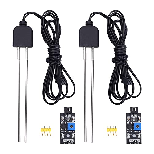
- 【Soil Moisture Meter】This probe measures soil moisture using analog resistance, making it a valuable tool for plant care…
- 【Easy to Read】This soil moisture detector produces a low signal on the DO port when the detected humidity exceeds the se…
- 【Adjustable Threshold】Rotate the blue potentiometer to adjust the detection threshold. Power and signal indicators on th…
Project 5: Basic Robotics with Motor Control
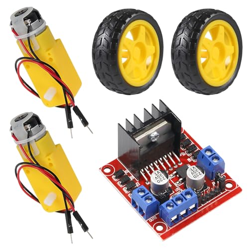
A two-wheel differential drive robot is the standard first robotics project on Pi. An L298N or L9110S H-bridge motor driver sits between the Pi GPIO pins and the DC motors, providing the current the motors need (GPIO pins cannot drive motors directly). The gpiozero Motor class abstracts the H-bridge control into forward, backward, and stop commands.
Hardware needed: Two DC gear motors with wheels, L298N H-bridge driver board, Pi 4 or Pi Zero 2 W, 4xAA battery pack (6V) for motors, jumper wires. Power the motors from the battery pack, not from the Pi’s 5V rail.
from gpiozero import Motor
from time import sleep

# L298N wiring: IN1=GPIO17, IN2=GPIO18, IN3=GPIO22, IN4=GPIO23
left  = Motor(forward=17, backward=18)
right = Motor(forward=22, backward=23)

def forward(speed=0.8, duration=1):
    left.forward(speed)
    right.forward(speed)
    sleep(duration)
    left.stop(); right.stop()

def turn_left(speed=0.6, duration=0.5):
    left.backward(speed)
    right.forward(speed)
    sleep(duration)
    left.stop(); right.stop()

def turn_right(speed=0.6, duration=0.5):
    left.forward(speed)
    right.backward(speed)
    sleep(duration)
    left.stop(); right.stop()

# Square pattern test
for _ in range(4):
    forward(duration=1)
    turn_right(duration=0.5)

print('Square complete')
Expected result: The robot drives a square pattern: forward 1 second, right turn, repeat four times. Adjust turn_right duration to calibrate 90-degree turns on your surface. Carpet and hard floor have very different friction coefficients.
See Raspberry Pi Projects for Beginners for lower-complexity GPIO builds before tackling motor control.


Project 6: Data Visualisation with Matplotlib
Raw CSV logs from the temperature logger and motion detector are more useful when plotted. This project reads the weather_log.csv from Project 1 and produces a time-series chart of temperature and pressure. The same pattern extends to any CSV-based sensor log.
import pandas as pd
import matplotlib.pyplot as plt
import matplotlib.dates as mdates

df = pd.read_csv('weather_log.csv', parse_dates=['timestamp'])
df = df.set_index('timestamp').last('24H')  # last 24 hours

fig, (ax1, ax2) = plt.subplots(2, 1, figsize=(12, 6), sharex=True)

ax1.plot(df.index, df['temp_c'], color='#B83E1C', linewidth=1.5)
ax1.set_ylabel('Temperature (C)')
ax1.grid(True, alpha=0.3)

ax2.plot(df.index, df['pressure_hpa'], color='#00917A', linewidth=1.5)
ax2.set_ylabel('Pressure (hPa)')
ax2.grid(True, alpha=0.3)

ax2.xaxis.set_major_formatter(mdates.DateFormatter('%H:%M'))
fig.autofmt_xdate()
plt.suptitle('24-Hour Weather Log', fontsize=14)
plt.tight_layout()
plt.savefig('weather_chart.png', dpi=150, bbox_inches='tight')
print('Saved weather_chart.png')
Expected result: A weather_chart.png file with two stacked time-series plots covering the last 24 hours of logged data. The chart updates each time you run the script against the growing CSV file. Schedule it with cron to generate a fresh chart every hour.
FAQ
Which sensors work directly with the Pi GPIO pins without an ADC?
Sensors with digital output work directly: DS18B20 (temperature, 1-Wire), DHT22 (temperature and humidity, single-wire protocol), PIR sensors (digital motion output), HC-SR04 (ultrasonic distance, digital trigger and echo), BME280 (temperature, humidity, pressure over I2C). Sensors with analog output (most soil moisture probes, light-dependent resistors, potentiometers) need an ADC chip like the MCP3008 between them and the Pi. The Pi has no built-in analog input pins.
Can I power motors directly from the Pi GPIO pins?
No. GPIO pins source a maximum of 16mA per pin and 50mA total across all pins. Even a small DC gear motor draws 100 to 500mA under load. Driving a motor directly from a GPIO pin will damage the Pi. Always use a motor driver (H-bridge) between GPIO and motors, and power the motors from a separate battery supply rather than the Pi’s 5V rail.
How accurate is the BME280 temperature sensor?
The BME280 datasheet specifies accuracy of plus or minus 0.5 degrees C over the 0 to 65 degree C range. In practice, results depend on placement. Mount the sensor away from heat sources including the Pi itself, direct sunlight, and motor components. In open air away from heat sources, readings are reliable to within 1 degree C of a calibrated reference. The Sense HAT’s onboard BME280 consistently reads 5 to 15 degrees C high due to heat from the Pi’s processor directly below it.
How do I run a sensor script automatically at boot?
Use systemd. Create a service unit file in /etc/systemd/system/ pointing at the venv Python binary and your script. Set After=network.target for scripts that need network access, and Restart=on-failure to restart automatically if the script crashes. This is more reliable than cron or rc.local for long-running sensor scripts. See Python Raspberry Pi for the full systemd service setup with a working example.
What is the difference between I2C and SPI for sensors?
I2C uses two wires (SDA and SCL) and supports multiple devices on the same bus using unique addresses. It is slower (typically 100kHz to 400kHz) but simpler to wire. SPI uses four wires (MOSI, MISO, SCLK, CS) and is faster (up to 10MHz on Pi) but needs a separate chip select wire per device. For most science project sensors, I2C is adequate. Use SPI for the MCP3008 ADC and for sensors that require fast sampling rates.
References
- https://gpiozero.readthedocs.io/
- https://datasheets.raspberrypi.com/camera/camera-module-3-product-brief.pdf
- https://www.bosch-sensortec.com/products/environmental-sensors/humidity-sensors-bme280/
- https://picamera2.readthedocs.io/
About the Author
Chuck Wilson has been programming and building with computers since the Tandy 1000 era. His professional background includes CAD drafting, manufacturing line programming, and custom computer design. He runs PidiyLab in retirement, documenting Raspberry Pi and homelab projects that he actually deploys and maintains on real hardware. Every article on this site reflects hands-on testing on specific hardware and OS versions, not theoretical walkthroughs.
Last tested hardware: Raspberry Pi 4 Model B (4GB), BME280 breakout, HC-SR501 PIR sensor, Camera Module 3. Last tested OS: Raspberry Pi OS Bookworm 64-bit. Python 3.11.2, gpiozero 2.0, picamera2 0.3.